I apparently had a folder of images prepared for technical grade shitposting that were going unused so it’s time for a SHITPOSTING FESTIVAL OF LIGHTS
This shitposting festival made possible by the PTek corporation.

In theory maybe this just means the top cover was put on backwards but I don’t want to open the top cover. Why? I don’t want to know what’s inside this unit because this is what was inside the older FM-500 series and it makes me a sad panda. (Spooling up turbocharger for powerful shitposting of… shit!)

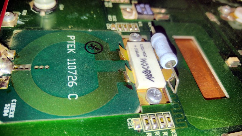
Here’s the PTek FM500 series pallet overall. Not visible, or even particularly accessible, above the top of this photo, is the control logic board buried between the heatsink and the housing. Input (and output) are the tiny white cables to the right. Input’s at the top. It first goes through a buffer/driver stage, a Wilkinson 2-port power divider, through the finals, through some very unusual stripline transformers, then to a Wilkinson 2-port combiner ending with the start of the output lowpass filter, a fourth-order pi network apparatus. Seems legit, but look at those RF FET modules.
Post continues to be image-heavy so I’m going to place a break here to avoid excessive page length
Look around you.
Look around you.
Just look around you.
Have you worked out what we’re looking for?

F U C K E R Y
NO REALLY WHAT IN THE ACTUAL FUCK IS GOING ON HERE
THEY ARE ALL SOLDERED LIKE THIS, WHAT

My only guess as to why this was done is they just didn’t have appropriate soldering equipment at the factory to handle the large devices!!! Proper installation would have the package leads FLAT to the board and soldered down like the tabs on the IPA transistor are. Actually, why did they get it right with the IPA then screw the pooch on the finals??!! Well, I mean, they ALMOST got it right with the IPA – the leads are curled which makes no sense but they’re at least completely inside the solder joint instead of… lying on top of it.

 I’m not even going to think too hard about this roached together heap of mica caps. Again, made to be soldered coplanar to the circuit board… not…. lying on their sides in a turd of solder.
I believe these are the caps to prevent the lovingly…. precisely…. bodged around a screwdriver handle? — inductors from shorting out the DC supply voltage… but seriously what in the actual fuck is this board design.
Perhaps they were just shoved in a corner to make room for those weirdass stripline transformers. See, those transformers run at a stunningly high voltage I’m guessing as they’re actually separate pieces of circuit board and there’s a layer of Kapton tape under them.
Here’s $5, go buy yourself some semi-flex coax for your transformers like every other properly designed amplifier uses. OY!!!


When installing that PTek Gamma shown above I had to adjust controls inside our oldschool STL receiver because it uses a really weird composite input level, I’ve never seen another exciter that required it set like this. There’s a control in software for the input gain but thanks to a severe software bug in the user interface it’s nigh unusable. There’s about a 1 in 32 chance that when you press raise or lower it has any effect and when it does it zooms off super fast.

This STL receiver is just… it’s… someone’s job security, I mean look at this glorious fuckery
- All resistors carbon composition (longterm drift)
- All ICs and transistors in cheap wipe contact sockets
- TANTALUM. CAPACITORS. EVERYWHERE.
- Pots that get scratchy when adjusted for the first time in years

note qei exciter serving in super critical passive rack shelf duty
Aaaaand let’s go revisit Linguini Mountain!


Much to my amazement, this Henry amplifier which has been a source of frustration to a sherriff’s department, the Forest Service, and a group of ham radio operators— about EIGHT different techs warned me to never switch it on— it appears to be separable into a big anodized aluminum shitbrick and a perfectly serviceable Astron 12v power supply. A diamond in the rough.
 So there are a few of these Silicon Valley Power Amplifiers kicking around here. Silicon Valley Power Amplifiers is now known as Delta RF and is out in Reno, Nevada– they are much better known for their solid state intermediate power amplifier modules used by Harris, Continental Electronics, and other manufacturers. Inside the lower box is basically two of their IPA blocks with power divider, combiner, lowpass, and control logic, but…… well….. about that control logic…..
It’s pretty clear they didn’t really entirely know what goes into building a successful standalone transmitter.
There’s no power control logic. None at all. No APC, not even a raise/lower on the remote interface. The only way you can adjust the output power is to adjust the drive. If you drive it too low, the Input Power In Range lights go out. I took this photo while it was suffering a bad under-drive condition. It really feels to me like this unit would be totally right at home as an external IPA for a tube transmitter, but as a standalone transmitter on air, it’s just….. too quirky. The power tends to drift low with no warning.
Oh, about that under-drive—-

And now…. at another site….
So I’ve worked with the wonderful products from QEI and PTek. Who else makes shit transmitters? What would my luck be to encounter THREE OF THEM ????
yeeaeaaarrggghhhh


I have another post in the queue about the issues plaguing Shasta County, California….. buuuut that’s another post entirely and may not even qualify as shitposting because it’s too thoughtful 😉


One thought on “Clearing out the “shitposts” folder”